
SATSAGEN v.0.9.0.1 article (English Google translated)
SATSAGEN INTERFACE
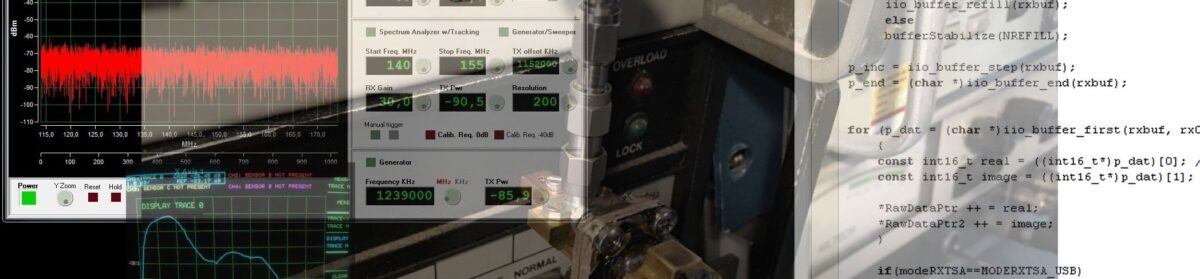
Franck F1SSF has produced an interesting PCB that collects all functions and schematics of the USBDAALBFER interface project (Video).
With SATSAGEN and Franck’s PCB, you can:
- Power a Noise Source for Noise Figure and Gain Analyzer measurements
- Drive an ADF5355 PLL synthesizer as a SATSAGEN TX device
- Connect AD831x log detectors to do power measurements up to 10 GHz
- Enable external analog and digital input for spectrum analyzer triggers
- Connect external SNAs thanks to a 10V pp ramp output synchronized with the SATSAGEN SNA/VNA scans
- Connect an RF switch to enable real two-port VNA operations
Download the Gerber files here or contact Franck F1SSF, but his PCB availability is limited.
Download the Arduino sketch here to compile and upload it to the interface.
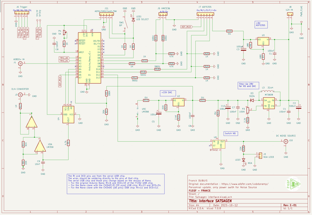
Follow Franck’s instruction steps to wire and make operational his SATSAGEN INTERFACE PCB:
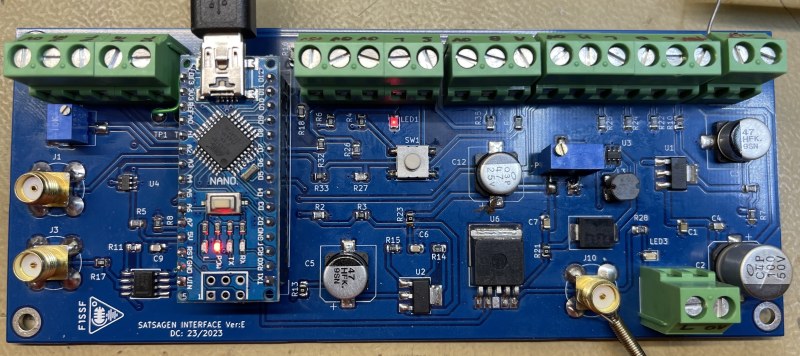
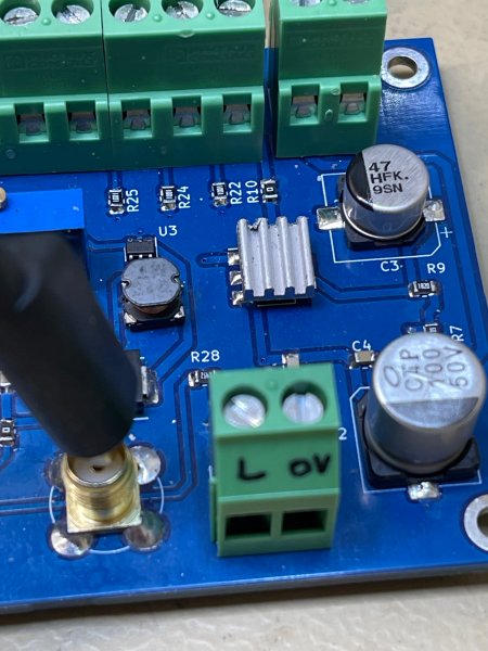
Hi All, Some information here. This PCBA is the first realization:
- Inserted components except Nano and resistors 0U:
- Use IBom:
- Power UP:
- Power supply on 12V IN connector
- ADF5355 power supply
- Measure R10 pad = 6V, if OK solder R10=0U
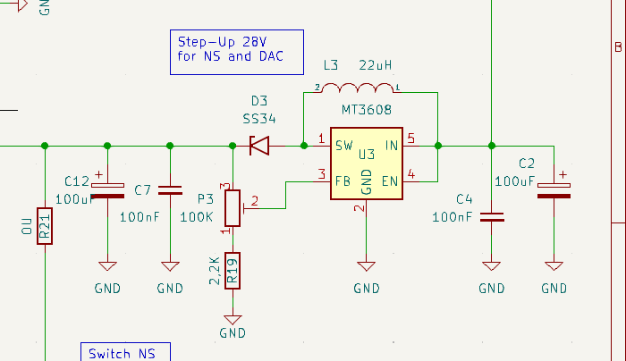
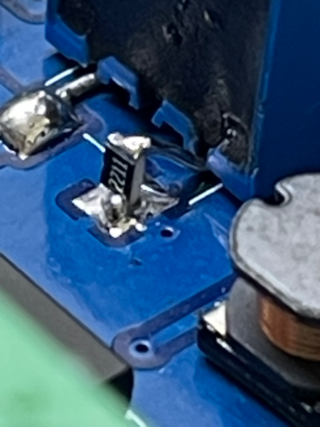
- Step Up 28V – Warning, add modify R19 as below picture
- Measure R23 pad, adjust P3 to obtain 28V max, If OK solder R23=0
- Detector Step Up = ON:
- Measure divider R2/R3, you must have 3Vmax
- +15V DAC
- Measure R13 pad = 15V, if OK solder R13=0U
- Power OFF
- Solder wires directly on serial chip Arduino (see schematic for pin numbers)
- Plug Arduino on support for removal easily, and solder wires DCD = TP1, RI=TP2
- Check the values of the ADF5355 voltage dividers
- R12/R22. R16/R24. R18/R25
- Now you can connect all peripherals
- Use connectors J6 , J11, J5, J7, J10
- +3V ref
- Adjust P4 to have +3V on Arduino pin ref N°18
- Configure Satsagen in tracking mode 0 to 6Ghz
- See on J3 voltage ramp from 0V to about 12V.
SW1 allows you to select the operating modes of the Arduino, depending on the use.
You can deport SW1, LED1, and LED3 on the front end with J11 and J9.
If you move the LEDs, then remove the SMD LEDs or if you leave them, then change the R6 and R22 to adapt the current. SW1 can stay on board.
J1 / J2 / J10 Footprints are BNC connectors, but you can use SMA connectors after cutting legs. You solder ground around directly around the body.
Because the ADF5355 consumes approximately 200mA, it is recommended not to exceed 12V power supply to reduce the dissipation of the 6V regulator. I added a small radiator with thermal glue.
If your RF switch HMC536 already contains 100U resistors on ports A and B under the shield, replace R34 and R35 with 0U.
73’s Franck F1SSF
SATSAGEN v.0.8.0.0
SATSAGEN v.0.8.0.0 article (English Google translated)
SATSAGEN v.07.2.0
Download Page
Highlights:
- Marker monitor by an audible tone
- A new reliable Waterfall
- Auto-export spectrum analyzer data
- Save/load SNA calibration data
- Restore window size and position saved at the application start
- Gesture on spectrum analyzer scope
- Spectrum analyzer resource monitor
Marker monitor
By enabling the marker monitor, an audible tone will be generated from the PC audio with frequency and intensity depending on the values of the marker currently selected in SATSAGEN. This function can be useful for calibrating signals or sources in amplitude/frequency without necessarily having to look at the PC screen. This feature is enabled by clicking on the ON button from the MKR Monitor panel from the SATSAGEN main window and is operative both in Spectrum Analyzer mode and in SNA or in VNA mode. It is also possible to use a Marker monitor even with a Log detector connected, in this case, there is no need to create a reference marker, as the monitor will work based on the immediate reading of the detector.
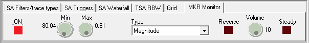
You can define the amplitude range with the Min and Max knobs. The amplitude range is -80 dBm to 0 dBm in the above example.
With the Type set to Magnitude, you will get an audible tone that will vary from 100Hz to 10kHz on a linear scale over the range -80dBm to 0dBm.
E.g., an about 5 kHz tone will be out if the selected marker indicates a -40 dBm signal. The volume of the audio tone will also follow the amplitude of the signal indicated by the marker in percent. So in the example above, the volume of the 5 kHz tone will be half the overall volume set with the Volume knob.
You can activate a flat volume with the Steady button if you do not want it to follow the amplitude of the marker.
The Reverse button reverses the tone scale. You will get a 10kHz tone with the -80dBm marker and a 100Hz tone with the 0dBm.
The types Frequency and Frequency to/from center configure the monitor to produce a tone related to the frequency locked by the marker rather than the amplitude. The Bandwidth field of the selected marker determines the frequency range of the above two types. These two types are allowed only in Spectrum Analyzer mode. A magnitude type is a default in SNA or VNA operations. Here is an example of using the Frequency types with the Spectrum Analyzer:
Create a new marker from the Edit SA markers table window:
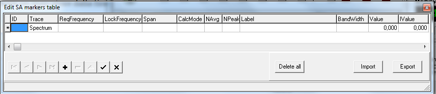
Fill in the ReqFrequency field with 145000000 and Bandwidth with 100000, for example.
The LockFrequency field is filled at the spectrum analyzer start. The LockFrequency field will be the strongest signal frequency inside the range of the Bandwidth field.
When the Marker Monitor is set to type Frequency, SATSAGEN generates a 100Hz of audible tone when the above marker has a LockFrequency field of 144,950 MHz. While a 10kHz tone will be generated at 145,050 kHz.
With the marker monitor activated of type Frequency to/from center, a 100 Hz tone will be generated if the detected signal is exactly at the required frequency of the marker, in the example 145 MHz, while 10 kHz tones will be generated if the signal found at 144.950 MHz or 145.050 MHz.
The Reverse function reverses the tone scale in both of the above types.
Waterfall
The new Waterfall of this version provides a fixed resolution configurable in Settings->Appearance instead of a dynamic resolution of the previous Waterfall. This means that any resizing of the window does not cause the waterfall to be reset.
From this version, it is possible to activate the Waterfall on an independent window rather than having it integrated into the main application window.
In the control panel of the new integrated Waterfall, there are the new Stand-alone, Max PeakH and Res Adapt controls:
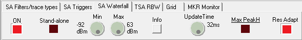
The Stand-Alone control starts the Waterfall on an independent Window.
The Max PeakH function allows the data acquired between one UpdateTime and another not to be lost. For example, if UpdateTime is set to 500ms and Max PeakH is off, every half second a line will be added to the waterfall with the spectrum of the instant, while with Max PeakH on each line will be the max hold of the last 500ms. By clicking on the label Max PeakH, it is possible to select an Average update process rather than a max hold.
The Res Adapt function adapts the data resolution to the pixel dimension of the waterfall window so that any signals present “narrower” than the video resolution is anyway displayed. If you use the zoom function, the Res Adapt function should be turned off to take advantage of the maximum detail available.
The functions just seen are also present on the Waterfall panel on an independent window:

Furthermore, the Vertical controls are available on this panel for orienting the Waterfall vertically, Levels for displaying the legend with the colors assigned for each signal amplitude, a Time Axis for displaying the abscissa with time information, Time Labels for a display of time labels inside the Waterfall, Hold to stop the display and finally ZReset to reset the zoom to the initial values.
Auto-export spectrum analyzer data
From this version, it is possible to set the automatic export of spectrum data in comma-delimited text format. There are all settings for this function In Settings->Logs/Export:
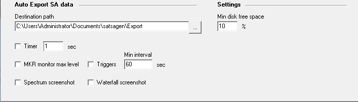
First of all, it is necessary to define a destination path for the text files that SATSAGEN will create before enabling the automatic export. Sets the desired path in the Destination path field and Min disk free space with the free disk threshold value.
Once the destination path and the minimum free disk threshold have been defined, the enabling takes place with the choice of the method with which the triggering of the automatic export will take place.
By enabling the Timer control, the export will take place at every interval in seconds specified in the adjacent field.
By selecting the MKR monitor max level, the export will be triggered when a signal monitored by the MKR monitor function (previously seen in the Marker monitor paragraph) reaches the level defined by the Max knob on the MKR monitor panel.
If the Triggers checkbox is selected, the export will take place as a result of the activation of one of the triggers set up in the SA Triggers panel.
Both the above MKR monitor max level and Trigger methods are conditioned by a minimum reactivation interval defined by the Min interval field, within which any triggers will be ignored.
The above methods are not exclusive, so any combination of Timer configuration, Triggers, and MKR monitor max level is allowed.
Finally, if the Spectrum screenshot and/or Waterfall screenshot controls are activated, the relative screenshots will also be taken with each automatic export that will be activated.
Save/load SNA calibration data
From this version, there is a function that allows the saving and loading of the SNA calibration data from a file.
This function is accessed via the menu items under File->Calibration data:
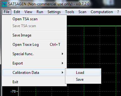
If you are using the VNA, the above menu items will act like the Load and Save buttons of the VNA Calibration panel.
Restore window size and position
By enabling the Restore saved window size and positions function from Settings->Appearance, the dimensions and position of the main window, of the integrated waterfall, and the independent window, will be saved when the application is closed and re-applied when it is restarted.
The maximized or minimized states of the main window will also be saved and restored when the application is restarted.
Gesture
By activating the Gesture enabled control from Settings->Appearance, the following gestures are available within the scope window of the spectrum Analyzer, provided that the mouse cursor is within the Scope of the Spectrum Analyzer but away from the edges and from any cursors present:
- Central frequency. The central frequency will vary with the defined steps by holding down the left mouse button and moving horizontally. Imagine viewing the spectrum as a sheet of paper: shifting to the left will increase the center frequency, and shifting to the right will decrease it.
- Span. By holding down the right button (or the middle mouse button) and moving horizontally, the span will increase in the left direction and decrease in the right direction.
- Zoom. Holding down any of the mouse buttons and simultaneously holding down the Ctrl key, vertical and horizontal mouse movement will respectively vertically and horizontally zoom the displayed spectrum. On touch screens, the horizontal zoom will be managed using the classic two-finger gesture on the screen.
The above gestures will work reversed If the Gesture reversed checkbox is enabled from Settings->Appearance. E.g., the central frequency will increase if you hold down the left mouse button and move it to the right.
Spectrum analyzer resource monitor
An automatic PC processing time control feature is enabled by default when the SATSAGEN spectrum analyzer is running. This function detects any exceeding of pre-set timeout thresholds, in particular on the acquisition and processing times of data from the SDR devices, and intervenes by progressively reducing the workload to bring the times back below the above thresholds to avoid slowdowns or hangs of the user interface. For example, this function can intervene by reducing the FFT size or turning off the Fast cycle when it detects that these settings can lead to slowdowns or blockages of the application. Automatic interventions are signaled with the opening of the trace log window and an explanatory message of the intervention.
It is possible to disable or re-enable this feature via the Settings->SA resource monitor menu.