
External Mixers

Starting with version 0.9.4, SATSAGEN can manage external mixers to extend the usable frequency range of supported devices.

Unlike the Converter RX and Converter TX parameters, which have been available in the device configuration since the early versions of the application, this new feature allows SATSAGEN to directly control the LOs of external mixers, while also giving the user detailed control over their configuration.

Configuration

In Settings, devices supporting this new feature have the EXT RX Mixer and EXT TX Mixer checkboxes in the Device Options tab.
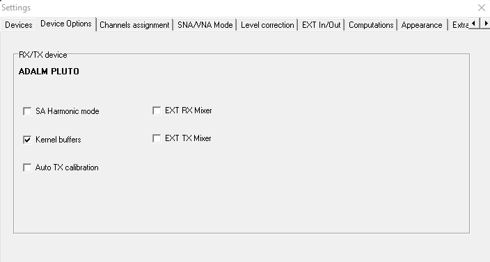
Enabling either of these options activates the corresponding functionality and makes the EXT RX Mixer and EXT TX Mixer tabs available, where the respective parameters can be configured.
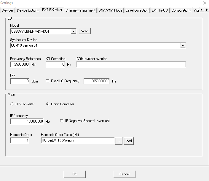
The EXT RX Mixer and EXT TX Mixer tabs are divided into two sections: LO and Mixer.

LO

The LO section is used to configure the Model, Device, reference frequency, and XO correction of the external mixer’s local oscillator.

In addition to the parameters normally available when configuring a device, it is also possible to specify the LO output level in dBm and optionally configure the local oscillator to operate at a fixed frequency.

Additionally, the LO section of the EXT TX Mixer tab includes a Shared checkbox. When selected, the EXT RX and EXT TX mixers can be configured to use a single shared LO. In this mode, the shared LO is configured exclusively in the EXT RX Mixer tab and is used by both mixers.

Mixer

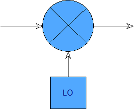
The Mixer section allows the user to select which conversion product is used:

  • UP-Converter: frequency addition
  • Down-Converter: frequency subtraction

The same section allows the user to configure the IF frequency and select which mixing product is used relative to the LO: positive (default) or negative.

When the negative product is selected, SATSAGEN automatically performs the required Spectral Inversion to ensure that the spectrum is displayed correctly.

If a fixed LO frequency is configured in the LO section, the IF Frequency and IF Negative controls are disabled because these options are not supported in this operating mode.

Finally, the Mixer section allows the user to specify the Harmonic Order, or alternatively a lookup table defining the Harmonic Order as a function of the tuning frequency. The Harmonic Order makes it possible to operate the mixer in harmonic mode according to the characteristics of the LO and the mixer.

Operation

When Fixed LO Frequency is selected, SATSAGEN tuning controls the local oscillator of the receiving or transmitting device.

When an IF frequency is specified instead (or an RF frequency in the EXT TX Mixer tab), tuning controls the LO of the external mixer, while the local oscillator of the receiving or transmitting device remains fixed at the frequency specified by IF Frequency (or RF Frequency in the EXT TX Mixer tab).

Startup

Once the EXT Mixer configuration has been completed, SATSAGEN can be powered on.

If the configuration is valid, SATSAGEN presents its usual operating interface. The application automatically extends the frequency range of the devices for which an EXT Mixer has been enabled, according to the configured parameters.

The user can therefore specify frequencies for the Spectrum Analyzer, Spectrum Analyzer with Tracking, VNA, Generator, and Sweeper transparently, without having to manage the external mixer separately.

Only the standard harmonic-mode functions of SATSAGEN are temporarily disabled, since harmonic operation is handled more efficiently through the external mixers and may also be incompatible with their configuration.

Correction Tables

When EXT Mixers are used, the device linearization and compensation tables use the following new, dedicated type codes:

  • Type 200 for RX compensation tables.
  • Type 200 and Type 202 for TX linearization tables.

When receiving with an EXT RX Mixer enabled, the correction process first applies the usual Type 0 compensation according to the frequency of the RX device LO, and then adds the Type 200 compensation according to the frequency of the external mixer LO, which corresponds to the actual tuning frequency.

When transmitting with an EXT TX Mixer enabled, the linearization process first applies the usual Type 0 linearization according to the frequency of the TX device LO, and then adds the Type 200 linearization according to the frequency of the external mixer LO (the actual transmission frequency).

If the TX Multiplier is also enabled, Type 202 is used instead.

Harmonic Order Table

As mentioned above, Harmonic Order Tables allow SATSAGEN to specify the Harmonic Order to be used as a function of frequency, providing runtime management of harmonic operation when external mixers are enabled.

Harmonic Order Tables use the INI file format, with sections named HO_ followed by a sequential decimal number starting from 1.

Each section contains:

  • f: frequency
  • h: Harmonic Order

The frequencies specified in the sections must be in ascending order.

The first section must define the minimum system frequency with Harmonic Order 1, while the last section must define the maximum system frequency with the highest Harmonic Order supported.

The following is an example of a valid Harmonic Order Table:

[HO_1]
f=485000000
h=1

[HO_2]
f=4850000001
h=3

[HO_3]
f=13650000001
h=5

[HO_4]
f=22450000000
h=5

For RX operation (the same criteria can also be applied to TX, with the only difference being that IF Frequency in TX corresponds to RF Frequency), the values in the Harmonic Order Table are determined by:

  • the frequency range of the external mixer’s local oscillator;
  • the configured IF Frequency;
  • the maximum Harmonic Order that can be reached;
  • the preferred harmonic to be used at each frequency range.

Therefore, before creating a Harmonic Order Table, it is important to have a clear understanding of these parameters, which are determined by the specific characteristics of the LO and the mixer.

In the example above, the external mixer’s LO is an ADF4351, with a frequency range from 35 MHz to 4400 MHz. The mixer has an optimum IF frequency of 450 MHz and supports harmonic operation up to Harmonic Order 5.

The HO_1 section therefore defines the minimum available frequency as 485 MHz (IF + minimum ADF4351 frequency) and specifies fundamental operation (Harmonic Order 1).

The last section, HO_4, defines the maximum available frequency as 22.45 GHz, calculated as the maximum ADF4351 frequency multiplied by Harmonic Order 5 and then combined with the IF:

4400 MHz × 5 + 450 MHz = 22.45 GHz

The intermediate sections define the transition points between harmonic orders. In this example, the third harmonic is used starting at 4.85 GHz, while the fifth harmonic is used starting at 13.65 GHz.

This allows SATSAGEN to automatically select the appropriate Harmonic Order during tuning, while transparently managing the external mixer and its LO.

Test, problems, and solutions for the SMA to IPEX cable for ADALM-PLUTO second channel


Another important piece written by Gianni IW1EPY about the long-standing problem of the IPEX-SMA cables used for the second channel of the ADALM-PLUTO. Here is his tutorial:


A set of different SMA female to IPEX was purchased from China:

Type 1. This is 5 cm long using RG178
Test result for the Type 1 cable
Type 2 using RG 1.13
Test result for the Type 2 cable. Sorry, it’s not smooth due to the fast sweep, but the reality remains.
Question: Is the IPEX connector the problem?
Using two SMAs coming from type 1 and using the correct cable RG316 for that connector, with the center cable in the hole and the braid soldered.
A good result is obtained.
Using an adapter for RG 1.13 with a good SMA connector
Test of 30 cm RG 1.13
Again a good result
What about the IPEX?

Same cable length, same SMA with adapter for RG 1.13 and an IPEX IPEX junction.
See also the channel 2 Pluto test of one of those cables.

This means that with a good SMA connection and a couple of IPEX, it can work up to 16 GHz.
First, no blame to the cable producer for usage up to 6 GHz is assured, but for us, that we take out the last still of lemon juice is not enough.
We use the second Rx as a reference for the VNA up to 12 GHz, so we would like a flat response in this range.
What is wrong?

These types of SMA cannot function properly; the correct Type 2 has many discontinuities and impedance changes that limit its use to around 6 GHz. On the left, Type 1 is its incorrect usage, as shown by my test with the proper coax cable. Inserting the entire coax cable, including the braid, into the SMA hole and soldering it is not correct. What happens? The tin solder connects the braid only at the rear entrance of the SMA, leaving a ground tube unconnected, which can be seen in the picture.

This insulated ground tube is responsible for the notch in the range from 6 to 8 GHz
Solution

Find the SMA with the correct cable hole to enter with the insulated central coax cable and solder the braid to the outside of the SMA.

For RG 1.13, use a small-hole SMA but avoid using too much solder; connect all the braid tube to the inner tube of the SMA.

Not the best, but usable

By now, the only solution to the problem is to purchase the IPEX cable and do the SMA connection.
Two good SMA-IPEX will allow the correct use of the second channel of ADALM-PLUTO up to 12 GHz.
Even without test systems is possible to use ADALM-PLUTO to make a comparison between cables to get the right one.

This is a bad cable with a large loss at 13,5 GHz
Again, bad, in this case at 11 GHz
This is the long RG 1.13 coming from the couple already tested (a twin cable used to validate the IPEX connector)
This is an RG 316 precrimped with IPEX in China and a China SMA for this type of cable.

Due to the stiffness of the cable is a bit longer to accommodate a larger bend of the cable vs the RG 178, which allows a shorter path but a worse performance.

73 51 de IW1EPY

Time Domain

Spectrum analyzers typically display signals in the frequency domain, but can also be configured to display in the time domain, a feature called Zero Span.

Satsagen has been equipped with Zero Span since version 0.8.0.0.

Starting with version 0.9.2.1, the Zero Span function has been expanded and improved. In summary, the display of frequency versus time has been added in addition to power versus time, and the processing mode is no longer only by FFT, but also by IF demodulation. E.g., this process mode allows display signals up to 2 uS per division using an RTL-SDR as a receiving device.

Zero Span is activated by clicking on the Time Domain (Zero Span) button located in the Spectrum Analyzer panel.

The TimeBase knob allows you to set the time base within the range allowed by the receiving device in use and the signal processing mode settings. By extending the bandwidth controls with a click on the BW label, you can also directly set the sampling rate expressed in MSPS:

At the same time as activating Zero Span, the Time Domain tab appears below the display, where other controls related to this function are available:

The Type list sets the display to power vs. time or frequency vs. time. The Processing mode list sets the processing mode to IF demodulation, ZERO IF demodulation, or FFT. The IF decimation list sets three decimation levels, 1, 10, or 100, which allow the time base to be extended over longer times if necessary in IF or ZERO-IF demodulation modes. The Trace auto-clear button only serves a purpose if a Trigger has been selected. If there is no signal at the Trigger and the Trace auto-clear button is activated, the display is cleared after a few seconds, while if the button is deactivated, the display “freezes” at the instant of the last Trigger.

The following image is of a setup with a double device. In reception, there is an RTL-SDR dongle, and in transmission, a HackRF. A small RF cable connects the two devices. The generator modulates a 100MHz carrier in AM at 20 kHz. Satsagen is configured for the classic spectrum display:

A classic spectrum analyzer display as a function of frequency. Note the carrier of an AM-modulated signal and the two sidebands.

By activating Zero Span with the same setup, the display switches to power vs. time, by setting Power vs. time from the Type list and IF demodulation from the Processing mode list:

Time domain visualization

The X-axis switches from a frequency to a time representation, while the Y-axis remains in amplitude expressed in dBm.

The image will not be still, but will scroll in one direction, as there is no synchronism between the modulation and the sampling performed. To synchronize and freeze the image, you need to activate a trigger from the Triggers tab.

The same view in the time domain, but with the Video trigger active

The Video trigger level setting, whether positive or negative slope, should fall within a value within the modulation amplitude, in this case from approximately -48 dBm to approximately -41 dBm.

If you can’t find an optimal trigger value to get a stable image, you can try to activate a sort of hysteresis by clicking repeatedly on the Level text above the knob until it becomes Level R and a Range knob becomes available for setting the trigger intervention range:

Time Domain Visualization with Trigger and Hysteresis Active

We now switch the Generator modulation to FMW, with the same modulation frequency as before and a deviation of 30 kHz.

To view the frequency modulation, you need to go back to the Time Domain tab and select Frequency vs. time from the Type list. Furthermore, from the Triggers tab, you need to set a level between approximately -30 kHz and +30 kHz:

Frequency vs. time display with trigger active

The X-axis remains in a time representation, while the Y-axis switches from a display of amplitude expressed in dBm to one expressed in frequency.

For correct viewing, you also need to adjust the bandwidth using the appropriate knob in the Spectrum Analyzer panel.

In the case of a frequency-modulated signal display, the minimum bandwidth value should be the maximum modulation frequency plus the deviation, multiplied by two. So in our case, the minimum bandwidth to ensure that the displayed shape does not suffer distortion is about 100 kHz.

Satsagen on Wine

Some functions and compatibility with the Linux Wine layer are improved starting from Satsagen version 0.9.3.5:

  • Simplified the Pluto connection by fixing the unable pluto.local address.
  • The serial COMx ports work now, so the Simple spectrum analyzers, PLL synthesizers, Log detectors, GPIB devices, and the spectrometers are now available.
  • The Pluto and GPIB terminal consoles work now.

Here is a step-by-step guide to take advantage of these improvements:

This guide is tested on Ubuntu 25.04 and Wine 9.0 layer. Some commands could be changed or adapted to different OS/Distribution versions.

  • Remove old Satsagen version if it is below 0.9.3.5. Open a terminal, type wine control, and choose the Add/Remove Programs icon to remove the old Satsagen Application
  • Close the Wine control panel. Download the latest Satsagen version from the Download Page, and unzip the file at the end.
  • Turn back on the terminal window, and type wine $HOME/Downloads/satsagen_9_3_5_setup.exe (or the version name you had downloaded), and execute it.
  • Complete the setup, show Apps, and click on the SATSAGEN icon to run the program. A message should be shown on the first run
  • Close the window and the application. Turn back on the terminal window and type groups yourusername.
  • If your username does not belong to the dialout group, add it by executing the sudo usermod -aG dialout yourusername
  • Restart Wine by typing winserver -k at the terminal prompt

  • So, connect a Pluto device, for example, to the PC, show Apps, and click again on the SATSAGEN icon to run the application
  • Wait for some seconds, let the USB device be detected by the OS, and click on View-> Open terminal menu, a dialog with a device available on the serial COM port should appear, confirming that the above procedure is successful.
  • Close the above window, and to check the Pluto connection, go to Settings -> Devices tab
  • A Pluto should be listed on the SDR Device listbox
  • Close the Settings window and click the Power button. Start the Spectrum Analyzer.