- GPIB support
- GPIB template
- PLL Templates
- Importing (and exporting) templates
- Device status control fields
- Start, end connection commands and alternative way to serial poll status byte
- Power Meter Template
- GPIB Terminal
- How Backspace Works in the GPIB Terminal
GPIB support
Using a GPIB->USB serial adapter like the AR488 project, Satsagen can drive devices with an IEEE488 GPIB/HP-IB interface.
Version 0.9.3.3 can drive synthesized generators and power meters as Satsagen TX and RX devices.
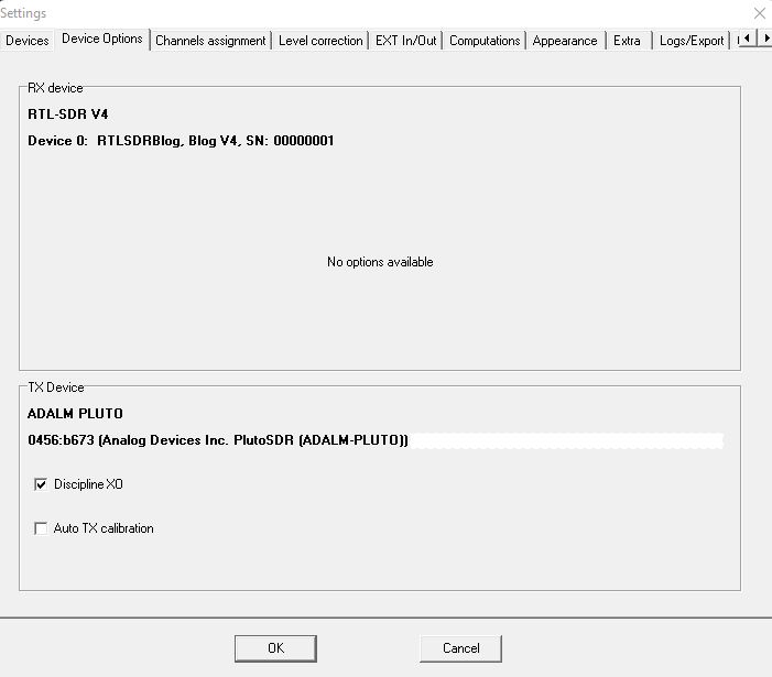
Some old devices are directly supported and are listed among the usable devices in Settings->Devices; other synthesized generators and power meters can be configured using two template models if you know their command syntax.
Why use Satsagen to drive GPIB/HP-IB devices?
In addition to simply acting as a remote control of devices, Satsagen can work as a link between multiple heterogeneous devices to create SNA/VNA instruments. E.g., Satsagen becomes a scalar SNA instrument by connecting a generator and a power meter both in GPIB/HP-IB, or an SNA/VNA by combining a GPIB/HP-IB generator and an SDR receiver such as ADALM-PLUTO.
With Satsagen, it is allowed to drive multiple GPIB/HP-IB devices using a dedicated interface for each device or with a single interface connected on a GPIB/HP-IB BUS where the devices to be controlled have different addresses, but it is not allowed to use two devices on the same GPIB/HP-IB BUS at the same time.
GPIB template
GPIB templates are configuration files in .ini format that allow Satsagen to drive devices on the GPIB bus.
In Satsagen version 0.9.3.3, there are two configuration models, one for driving synthesized generators and another for power meters.
In the Documents\Satsagen\Settings directory, you will find two template files that you can copy and modify to suit your needs to generate the final templates to import into Satsagen: templatePLL_commented.ini for synthesized generators and templatePM_commented.ini for power meters.
Then copy the templates with a name of your choice into the same “Documents\Satsagen\Settings” directory, and edit them with Notepad.
PLL Templates
PLL templates allow Satsagen to drive synthesized generators on the GPIB bus. They have a unique section called CUSTOMGPIBPLL.
The mandatory fields that need to be customized to drive the generators synthesized on GPIB are:
- DeviceAddr: GPIB address
- fGEN: initial frequency in Hz. It can be changed from the Satsagen Generator panel. For example, put a frequency of your choice in the range of the device.
- TXAttGEN: Initial attenuator setting in dBm. This parameter can also be changed from the Generator panel. For example, set a value to obtain the lowest possible initial output power.
- XO_FREQUENCY: reference frequency in Hz. Most devices use a reference frequency of 10 MHz, so fill in with 10000000.
- REFTXPWR: Fill with the maximum output power of the device expressed in dBm
- MINFREQTX: compile with the minimum frequency in Hz allowed by the device
- MAXFREQTX: Compile at the maximum frequency in Hz allowed by the device
- MINTXATT: Fill in the dB value of the device attenuator to get the minimum output power. For example -110
- MAXTXATT: Fill in the dB value of the device attenuator to get the maximum output power. Usually, this should be set to 0
- TXATTNSTEP: Fill in the dB granularity of the device attenuator, usually 10, 1, or 0.1
- CmdCWON: command to activate output, for example, RF1
- CmdCWOFF: command to turn off output, for example, RF0
- CmdDefSetPwrOut: command to set the output level of the device. For example PL followed by one of the following Satsagen variables and usually terminated by the suffix DB: %PWRDBMDEC% will be replaced with the value in dBm including the sign and a decimal, %PWRDBMINT% will be replaced with the integer value in dBm including the sign or %PWRDBMSIGN% which will be replaced only by the sign character. An example command could be PL%PWRDBMDEC%DB, Satsagen will then send the device to set an output value of, for example, -30 dBm, the command PL-30.0DB in this case.
- CmdDefSetVFO: Command to set the device frequency in Hz. For example, CW#SATSAGENVARIABLE#HZ, where #SATSAGENVARIABLE# can be: %FREQGHZDEC% for full frequency in GHz with decimals, for example, 10.368200125. %FREQGHZ% frequency in GHz only, for example 10. %FREQMHZDEC% full frequency in MHz with decimals, for example 10368.200125. %FREQMHZ% frequency in MHz without decimals, for example 10368. %FREQMHZONLY% represents only the MHz portion, for example, 368 if the full frequency in GHz is 10.368200125. %FREQKHZDEC% full frequency in kHz with decimals, for example 10368200.125. %FREQKHZ% frequency expressed in kHz without decimals, for example 10368200. %FREQKHZONLY% only the portion in kHz, for example, 200. %FREQHZ% complete frequency expressed in Hz, for example 10368200125. %FREQHZONLY% only the portion in Hz, for example, 125. An example command could be: CW%FREQHZ%HZ, Satsagen, then to set the frequency in the example 10368200125 Hz, the following string: CW10368200125HZ.
A minimal template INI file for working with synthesized generators might therefore look like this:
[CUSTOMGPIBPLL]
DeviceAddr=19
fGEN=2000000000
TXAttGEN=-60
XO_FREQUENCY=10000000
REFTXPWR=12
MINFREQTX=2000000000
MAXFREQTX=18000000000
MINTXATT=-110
MAXTXATT=0
TXATTNSTEP=1
CmdCWON=RF1
CmdCWOFF=RF0
CmdDefSetPwrOut=PL%PWRDBMDEC%DB
CmdDefSetVFO=CW%FREQHZ%HZ
Importing (and exporting) templates
Import the above file into Satsagen’s memory to make the template configuration operational.
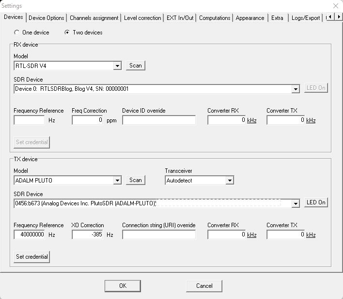
From the Devices tab in Settings, choose GPIB/Custom PLL Synthesizer from the Model list and import the .ini file using the Load Template button.
If the syntax check is successful, Satsagen will display a confirmation message confirming the import. The GPIB/Custom PLL Synthesizer device can be used with the newly created configuration in subsequent sessions.
Re-importing another file using the Load Template button will cause the configuration to be overwritten in memory.
The active configuration in memory can be exported to an .ini file using the Export Template button. It is also possible to export the contents of the configuration in memory to an existing .ini file; this can be useful to preserve any comments not present in memory and that would be lost if you exported the configuration to a new file.
Many other fields can be used in a template to optimize the GPIB device operations and add functionality.
Device status control fields
If the device allows it, the fields that verify the PLL lock status of the synthesized generator should be added. This check is necessary if, following the sending of commands such as ON and OFF of the CW, setting of the output power and frequency, the device does not provide an automatic lock check after receiving commands. In such conditions, the control may not work correctly, generating errors or application crashes during use.
The most common method for verifying the PLL lock is by testing a bit of the device’s status byte (or word).
The PhaseLockedStatusMask and PhaseLockedStatusBitNegate fields define how to test the status bit for PLL lock verification.
The PhaseLockedStatusMask field defines the mask to “extract” the bit from the status. For example, if the bit indicating the PLL lock weights 16, the mask should be set to PhaseLockedStatusMask=16 (or 0x10 in hexadecimal). If the device flags that the PLL lock occurs when the above bit is zero, with a negated logic, then we should set PhaseLockedStatusBitNegate =1.
An alternative methodology to test the PLL lock offered by Satsagen in case the status byte (or word) does not provide it, is to send a command and analyze the result of that command. With the CmdGetPhaseLocked field, we define the command to send to the device, and with RegEx2MatchMessagePhaseLocked, the regular expression to use to match the result when the PLL lock occurs. For example, if the command to test the PLL lock is LOCK?, then we set CmdGetPhaseLocked=LOCK?, and if the answer is simply the number 1 for the lock and 0 for the unlock, then we will have to set RegEx2MatchMessagePhaseLocked=[1]. If CmdGetPhaseLocked is defined, the mask on the status byte seen previously will have no effect.
It is also possible to adjust the timing of the aforementioned lock verification mechanism, whether using the status byte or a command. Using the timeoutPhaseLock field, we define the timeout in milliseconds after which, if the above methods have not detected the lock, the procedure goes into error and the application stops, informing the user. With usSleepPhaseLockWaitCycle, we define the wait in microseconds between one test and the other until a positive response is received or the timeout seen previously expires. This parameter is useful for not needlessly overloading the device with requests.
In the worst case scenario where the device does not provide any method to check the lock status, it is possible to insert a fixed delay in milliseconds after sending the commands, quantifiable based on checks that should be performed manually, for example by sending the commands with the GPIB terminal available in the Satsagen application. These delays can be specified with the following fields:
msSleepAfterCWTurnONOFF wait in milliseconds after sending CW ON or OFF command
msSleepAfterSetPwrOut wait in milliseconds after sending the power output command
msSleepAfterSetVFO waits in milliseconds after sending the set frequency command
Identical in syntax to the lock check just seen, there are as many fields available to inquire the device’s ready status, which can be used before sending new commands. In order, DeviceReadyStatusMask, DeviceReadyStatusBitNegate, CmdGetDeviceReady, RegEx2MatchMessageDeviceReady, timeoutDeviceBusy, and usSleepDeviceBusyWaitCycle.
Always similar in syntax, the following fields are also available for checking for errors: ErrorStatusMask, ErrorStatusBitNegate, CmdTestError, and RegExTestError. In this case, the parameters related to timeouts and waits could not be used, while two fields allow you to read from the device a description of the error just encountered: CmdGetError and RegExGetError.
The above control fields for lock, device ready, and error presence must be activated in the “sections” relating to the main commands of CW ON and OFF, output power setting, and frequency setting. This is done by setting the fields testPhaseLockedxxx, testDeviceReadyBeforexxx, testDeviceReadyAfterxxx, and testErrorxxx to 1.
The configuration example for a PLL template seen previously will become the following, complete with lock, ready, and error control fields:
[CUSTOMGPIBPLL]
;;;Definizione generale del dispositivo
DeviceAddr=19
fGEN=2000000000
TXAttGEN=-60
XO_FREQUENCY=10000000
REFTXPWR=12
MINFREQTX=2000000000
MAXFREQTX=18000000000
MINTXATT=-110
MAXTXATT=0
TXATTNSTEP=1
;;;Definizione dei test su lock PLL, device ready ed error
PhaseLockedStatusMask=16
PhaseLockedStatusBitNegate=1
timeoutPhaseLock=3000
usSleepPhaseLockWaitCycle=20000
;;;-------------------------------------------------------
DeviceReadyStatusMask=8
DeviceReadyStatusBitNegate=0
timeoutDeviceBusy=3000
usSleepDeviceBusyWaitCycle=20000
;;;-------------------------------------------------------
ErrorStatusMask=2
ErrorStatusBitNegate=0
;;;Definizione dei comandi principali e attivazione dei test
testDeviceReadyBeforeCWONOFF=1
CmdCWON=RF1
CmdCWOFF=RF0
testErrorCWONOFF=1
testDeviceReadyAfterCWONOFF=1
testPhaseLockedCWONOFF=1
;;;---------------------------------------------------------
testDeviceReadyBeforeSetPwrOut=1
CmdDefSetPwrOut=PL%PWRDBMDEC%DB
testErrorSetPwrOut=1
testDeviceReadyAfterSetPwrOut=1
testPhaseLockedSetPwrOut=1
;;;---------------------------------------------------------
testDeviceReadyBeforeSetVFO=1
CmdDefSetVFO=CW%FREQHZ%HZ
testErrorSetVFO=1
testDeviceReadyAfterSetVFO=1
testPhaseLockedSetVFO=1
Finally, among the device status control fields (which only have a visual function) are those that allow you to read the temperature or monitor the oven of the device’s reference crystal, updating the color and information in the main Satsagen window via the LED located next to the Power On button.
Specify with CmdReadTemp the command to send to obtain the device temperature, for example, CmdReadTemp=TEMP?. At the same time, specify RegEx2DecodeMessageReadTemp with the regular expression that allows to extract from the response to the previous command the temperature value including sign and decimal part, for example, RegEx2DecodeMessageReadTemp=([-+]?\d+(?:.\d+)?)
If the device does not provide a temperature reading command, but via a status byte bit if the oven of the reference crystal has reached the operating temperature, then OvenStatusMask can specify the mask of the bit in question, for example if it is the bit with weight 4, OvenStatusMask=4 and if it is negated, i.e. zero when the oven is at temperature, add OvenStatusBitNegate=1.
Start/end connection commands, and an alternative to serial poll
With the CmdInit and CmdEndConn fields, you can specify any commands to send to the device when connecting and disconnecting Satsagen. With CmdInitResponseToTrace=1, you activate the sending of the response of the CmdInit command to the trace log; this can be useful if the CmdInit sends a command to query the device version, which can then be read in the Satsagen trace.
Finally, it is possible to have Satsagen use an alternative method to the GPIB serial poll to read the status byte (or word), if available from the device. With the CmdGetDeviceStatus field, you define the command to send to obtain the status byte, and with RegEx2DecodeDeviceStatus, the regular expression to use to match the numerical value of the status byte, RegEx2DecodeDeviceStatus=\d?, for example.
Power Meter Template
Power Meter templates allow Satsagen to drive Power Meters on the GPIB BUS. They have a unique section called CUSTOMGPIBPM.
The mandatory fields that need to be customized to drive the Power Meters on the GPIB BUS are:
- DeviceAddr: GPIB address
- REFGAIN0: offset from reading. With this field, we can specify an offset in dB that Satsagen will apply to the reading before displaying it. Normally, REFGAIN0=0 should be set to zero, but it can be set to an offset value for device calibration if the device does not provide it internally.
- MINFREQRX: Specify with this field the minimum frequency in Hz of the Power Meter device.
- MAXFREQRX: Specify with this field the maximum frequency in Hz of the Power Meter device.
- MAXINPUT: indicates the maximum power allowed by the Power Meter, expressed in dBm
- DYNAMICRANGE: the dynamics of the Power Meter expressed in dB. For example, with DYNAMICRANGE=106 and the previous field MAXINPUT=6, the Power Meter can measure from -100 dBm to +6 dBm.
- nreadsmeanTSA: is the number of readings for calculating the average for each TSA scan point if the Power Meter is used as an RX device in an SNA configuration, i.e., combined with a second device with the role of TX, tracking generator.
- CmdReadPwr: This is the command to send to the device to perform the power reading.
- RegEx2DecodeMessageReadPwr: is the regular expression to use to extract (match) the reading value from the response of the previous command (CmdReadPwr).
A minimal template INI file for operation with Power Meters could therefore look like the following:
DeviceAddr=8
REFGAIN0=0
MINFREQRX=1000000
MAXFREQRX=200000000
MAXINPUT=6
DYNAMICRANGE=106
nreadsmeanTSA=1
CmdReadPwr=IPW,TRG
RegEx2DecodeMessageReadPwr=([-+]?\d+(?:\.\d+)?)
The control fields CmdGetDeviceReady, DeviceReadyStatusMask, CmdTestError, and CmdGetError, already seen in the previous chapter of the PLL template, can also be used with the same syntax in the configuration for the Power Meters. The fields that activate the controls for the Power Meters are: testDeviceReadyBeforeRead, testErrorRead, and testDeviceReadyAfterFailedRead.
The above configuration example will then become the following if the control fields are completed:
;;;Definizione generale del dispositivo
DeviceAddr=8
REFGAIN0=0
MINFREQRX=1000000
MAXFREQRX=200000000
MAXINPUT=6
DYNAMICRANGE=106
nreadsmeanTSA=1
;;;Definizione dei test su device ready ed error
DeviceReadyStatusMask=8
DeviceReadyStatusBitNegate=0
timeoutDeviceBusy=3000
usSleepDeviceBusyWaitCycle=20000
;;;-------------------------------------------------------
ErrorStatusMask=2
ErrorStatusBitNegate=0
;;;Definizione del comando principale e attivazione dei test
testDeviceReadyBeforeRead=1
CmdReadPwr=IPW,TRG
testErrorRead=1
RegEx2DecodeMessageReadPwr=([-+]?\d+(?:\.\d+)?)
testDeviceReadyAfterFailedRead=1
Finally, it is also possible to use the following fields, identical in syntax to those already seen in the previous chapter, PLL Template:
CmdInit, command sent when connecting, and CmdInitResponseToTrace, if it is 1, it sends the CmdInit response to the trace log. CmdEndConn, command sent when disconnecting. CmdGetDeviceStatus, the alternative command to the serial poll status byte, and RegEx2DecodeDeviceStatus, a regular expression to match the numerical value of the status. CmdReadTemp is the command to read the device temperature, and RegEx2DecodeMessageReadTemp is to extract the double value of the temperature with a regular expression. OvenStatusMask, an alternative to the previous command, status bit that determines if the oven is at temperature, and OvenStatusBitNegate to deny it.
GPIB Terminal
Satsagen includes a terminal with which you can “talk” to the device connected to GPIB for debugging/troubleshooting purposes.
To open the terminal, click Open GPIB terminal from the View menu, even with Satsagen in Power Off.
At this point, the application will present a list of available interfaces:

Select the desired interface and double-click or click Ok.
Once connected, a terminal will open in verbose mode from where you can send commands either to the interface (preceded by ++) or directly to the device at the default address, 1.

To change the address in use, give the command ++addr x , where x is the GPIB device number. With ++help, we get the list and description of the interface commands preceded by ++. For a complete description, refer to the AR488 documentation.

Remember to close the terminal at the end of the operations to free up the serial port, to let Satsagen connect to the device and control it.
How Backspace Works in the GPIB Terminal
You will probably find that the backspace key has no effect when using the terminal, or the cursor appears to move back, but in the line buffer, this does not happen, so if you use it to correct a command, it will still be sent to the device incorrectly.
To solve this problem, you need to edit the AR488.ino file in the AR488 sources and add the following lines that enable backspace to work.
 // handle the backspace in verbose mode - albfer 21/12/2024
      case 0x7f:
      case 0x8:
      if(isVerb && pbPtr)
        pbPtr--;
        else
        {
        addPbuf(c);
        isEsc = false;
        }
      break;
The above lines should be inserted inside the parseInput(char c) function, from the line following switch(c){ to obtain the first lines of this function in this way:
uint8_t parseInput(char c) {

  uint8_t r = 0;

  // Read until buffer full
  if (pbPtr < PBSIZE) {
    if (isVerb && c!=LF) dataPort.print(c);  // Humans like to see what they are typing...
    // Actions on specific characters
    switch (c) {
      // handle the backspace in verbose mode - albfer 21/12/2024
      case 0x7f:
      case 0x8:
      if(isVerb && pbPtr)
        pbPtr--;
        else
        {
        addPbuf(c);
        isEsc = false;
        }
      break;
      // Carriage return or newline? Then process the line
      case CR:
      case LF:
.
.
.
Recompile with the Arduino environment and reload to the interface.