Download Page
This version includes the VNA feature.
To run the VNA feature are required an ADALM-PLUTO Rev.C/D or a Pluto+ and a bridge or a directional coupler!
From this version, SATSAGEN will not perform the Pluto frequency range extend anymore at the first power on by default. The user could choose the preferred transceiver from Settings->Devices now.
SATSAGEN VNA
Setup guide and basic operations
Minimal prerequisites:
- One ADALM-PLUTO Rev.C/D upgraded to >=0.33 firmware version.
or
- One Pluto+ with the firmware shipped with Pluto+ and provided by the vendor
- An SMA-based directional coupler or directional bridge with the proper specifications of the frequency range, directivity, and coupling factor is needed.
- One short female to female IPEX4 cable or one male to male SMA cable
- One male to male SMA cable
- One male to male SMA adapter
- A VNA calibration kit consists of Short, Open, and Load SMA adapters.
- Two SMA attenuators as optionally
Hardware setup:
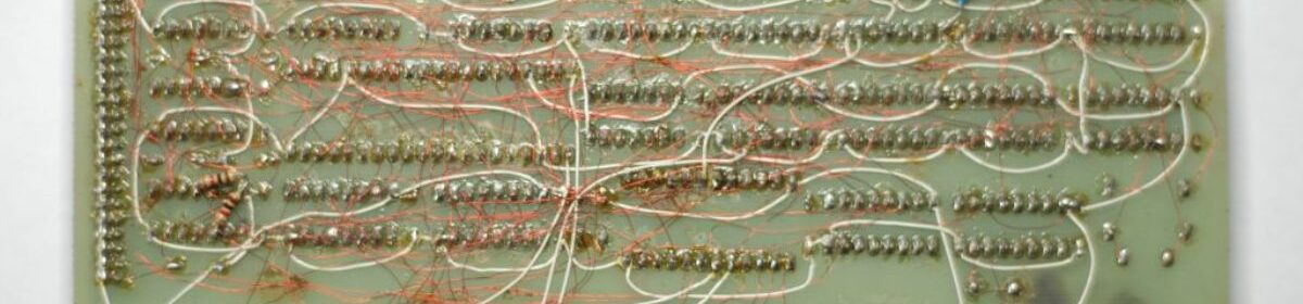
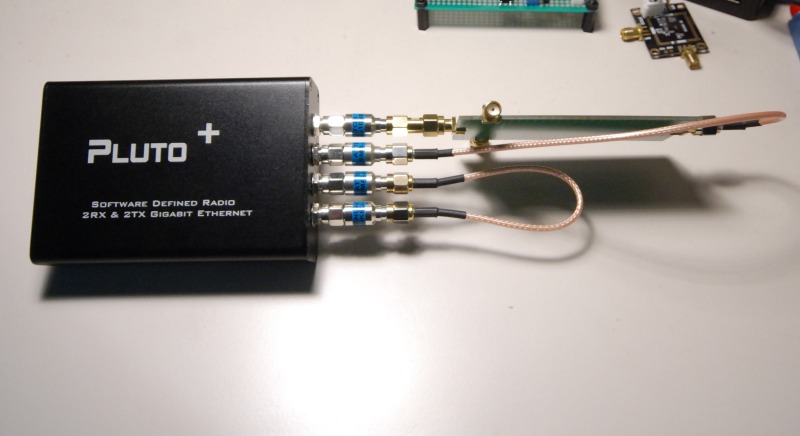
- Connect Pluto’s RX/TX internal 2nd channel ports with the F/F IPEX4 loopback cable. I used an F/F IPEX4 cable with a homemade attenuator. The attenuator is optional.
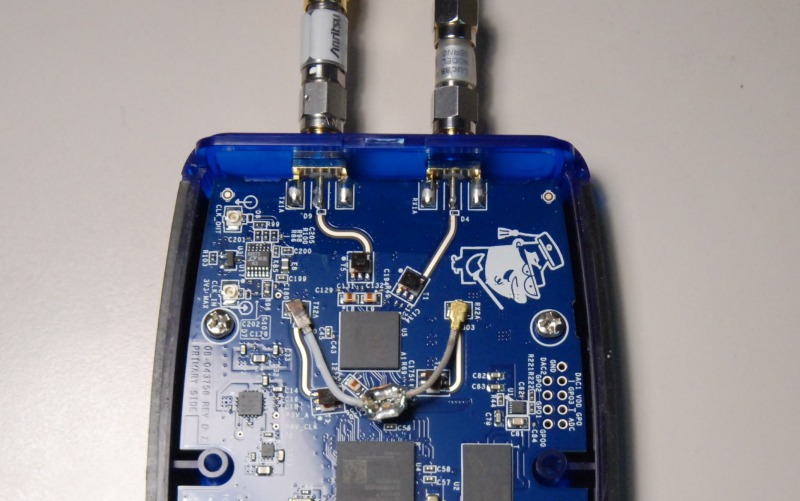
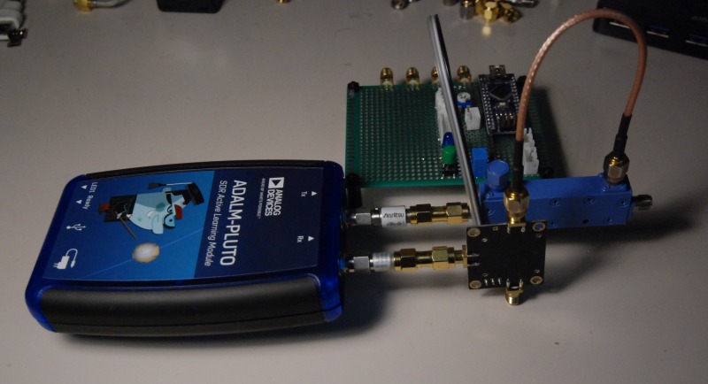
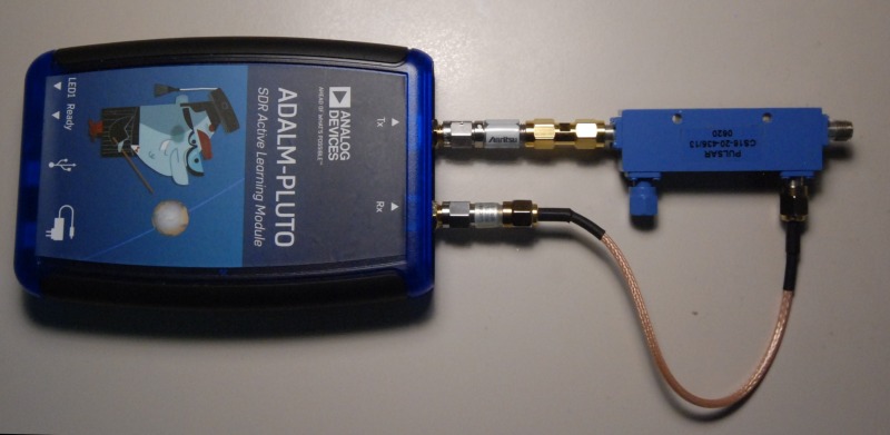
- Connect the directional coupler to Pluto, as shown in the image. The attenuators are also optional in that case. I used a 16dB SMA 2-18GHz directional coupler in this example.
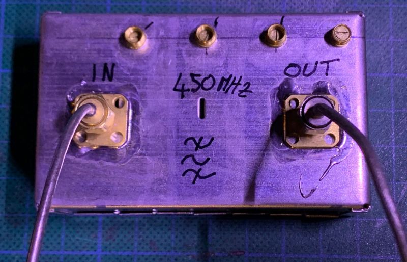
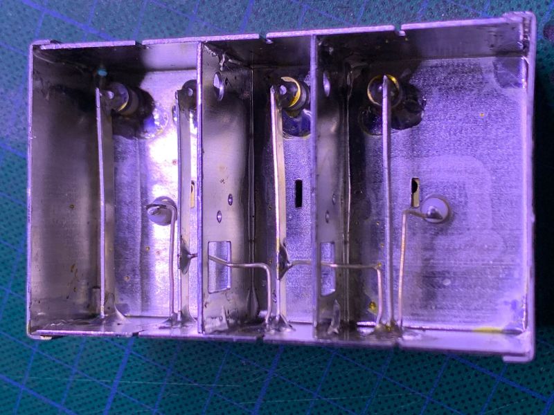
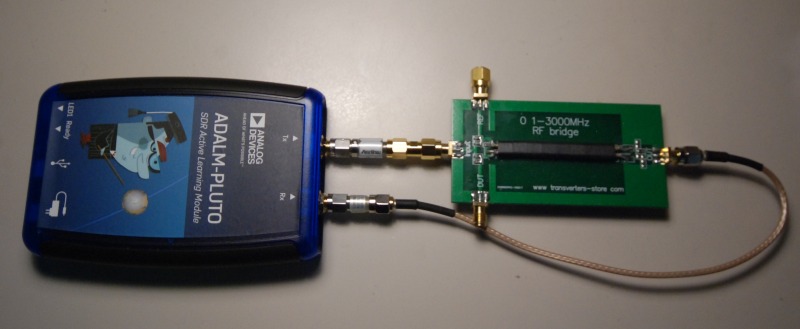
- There is a setup example in the below image with a cheaper bridge working until about 1,5 GHz.
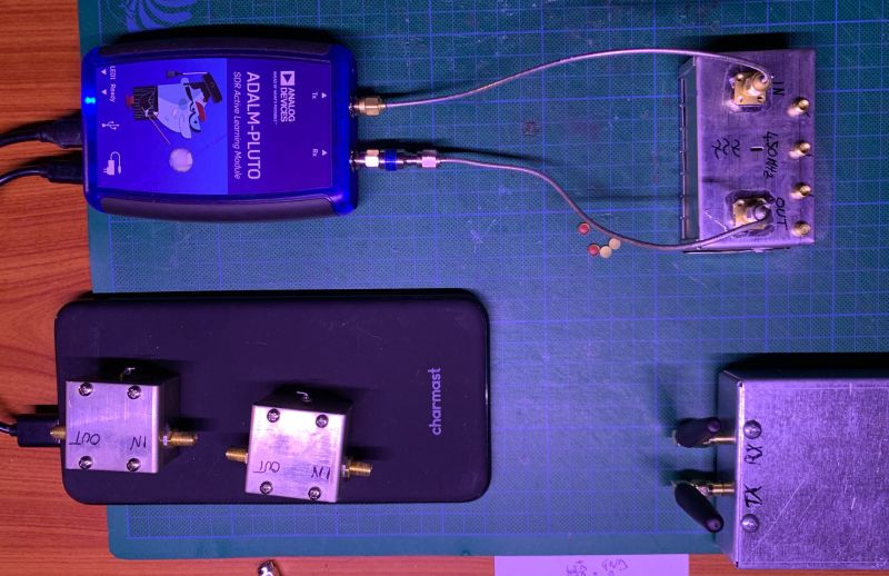
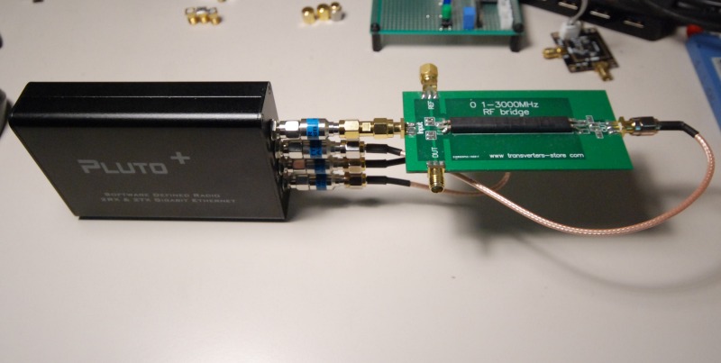
- Another setup example with the Pluto+ device
Software setup steps to do only the first time:
- Run SATSAGEN on fresh installation and go to Settings
- Select Model to ADALM PLUTO and Transceiver to AD9361 + 2r2t
- Connect the Pluto to the computer’s USB port
- Wait until the computer recognizes the device. Next, press the Scan button. The Pluto device should appear on the SDR Device control.
- Click OK to close the Settings page.
- Press the Power button, and the Pluto config phase should start.
- The grid should appear in about 15 seconds.
- Back to the Settings page and go to SNA/VNA Mode tab.
- Select Mode to VNA
- Go to the Level correction tab.
- Set the TX level offset and RX level offset with the values of the attenuators eventually connected to Pluto’s external ports. Be sure to enter negative values or press the Loss controls.
- Set the 2nd Channel – TX level offset with the value of the attenuator eventually present on the F/F IPEX4 loopback cable.
- Click OK to close the Settings page.
A calibration example:
- Click the Power button to power on SATSAGEN.
- Set the Start Freq. MHz and Stop Freq. MHz with a range frequency desired (depending on the directional coupler frequency range). E.g., Start Freq. = 1000 MHz and Stop Freq. = 3000 MHz
- Set the Resolution to 100 points initially.
- Start VNA by clicking on the VNA button.
- Connect the Short SMA adapter (from the VNA calibration kit) to the directional coupler port.
- Press the Short button on the VNA Calibration tab and wait until it goes to green color.
- Disconnect the Short SMA adapter and connect the Open SMA adapter now.
- Press the Open button on the VNA Calibration tab and wait until it goes to green color.
- Disconnect the Open SMA adapter and connect the Load SMA adapter now.
- Press the Load button on the VNA Calibration tab and wait until it goes to green color.
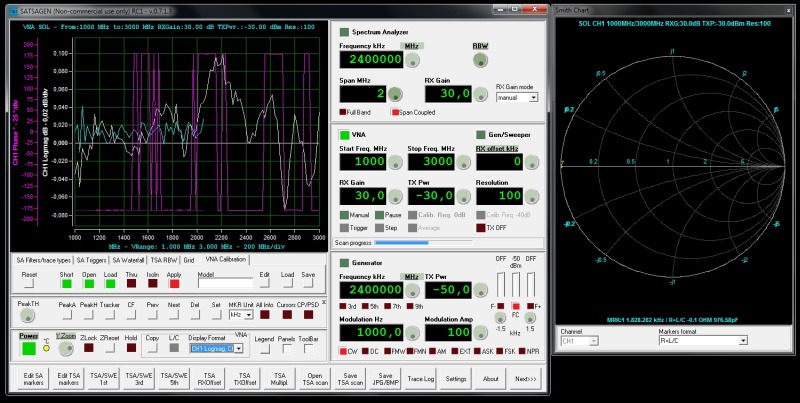
- Press Apply on the same VNA Calibration tab, and a single point and marker should appear on the Smith chart center.
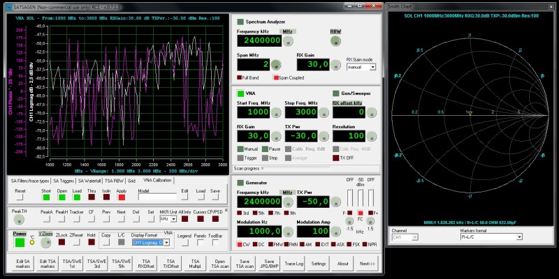
- Disconnect the Load SMA adapter and connect the Open SMA adapter to the directional coupler. A point or a little segment should appear on the Smith chart open circuit region.
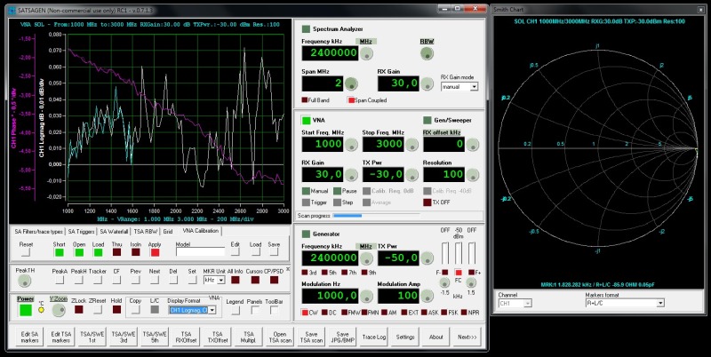
- Disconnect the Open SMA adapter and connect the Short SMA adapter to the directional coupler. A point should appear on the Smith chart short circuit region.
A “semi-two-port” VNA operation is possible with the above setup. It means that one port at a time measuring is possible.
The first channel of the display format selected determines what port you use. E.g., Port 1 (or CH1, or S11) is measured if the CH1 Logmag, CH1 Phase display format is specified. Work on Port 2 (or CH2, or S21) when the CH2 Logmag, CH2 Phase display format is selected. The same rule is valid for the Custom Display Format. The Main trace setting determines the port used. The 2nd and 3rd trace settings must follow the channel selected by the main trace.
An RF switch and related interface can enable effective two-port VNA operations, allowing free display format combinations. No manual processes are longer needed to pass from one port to another.