
You can build your waveguide filter and amplifier
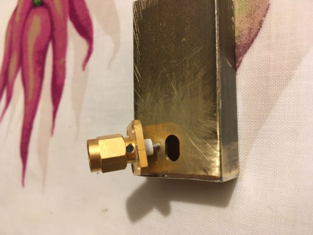
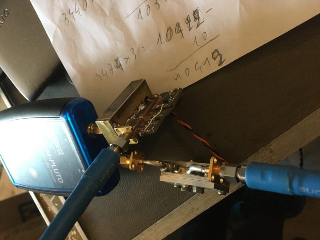
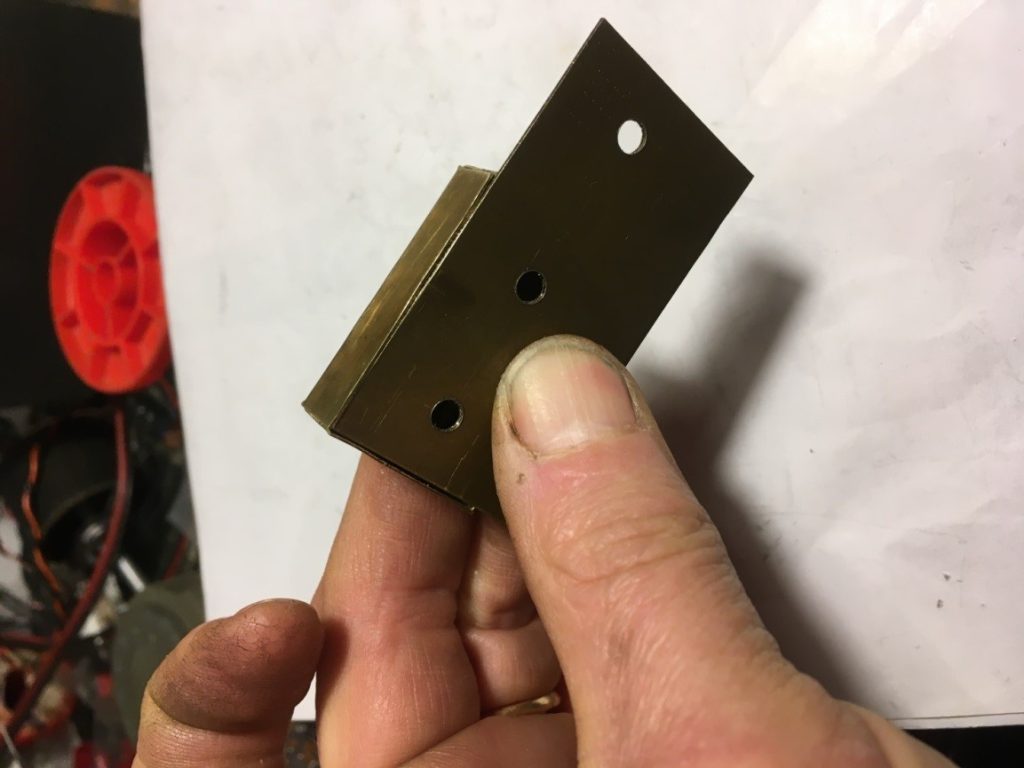
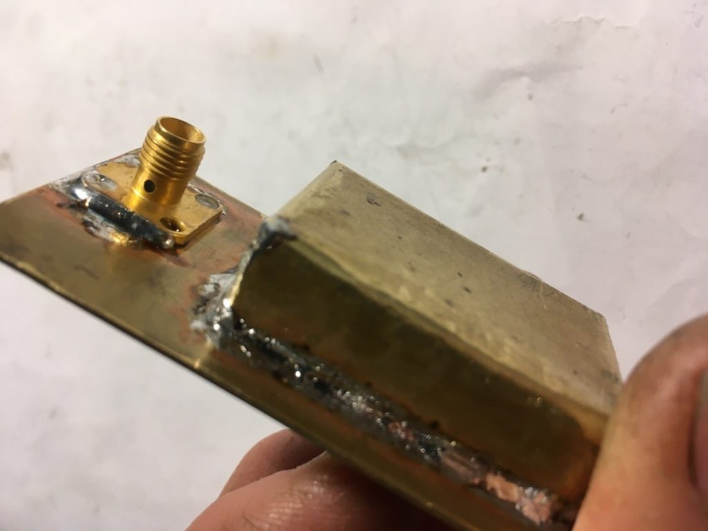
This is a Brass profile similar in dimension to an std waveguide WR90.
The cut-off frequency, the frequency at which the energy starts propagating inside the guide, depends on the guide dimension, in this case, 6.5 GHz.
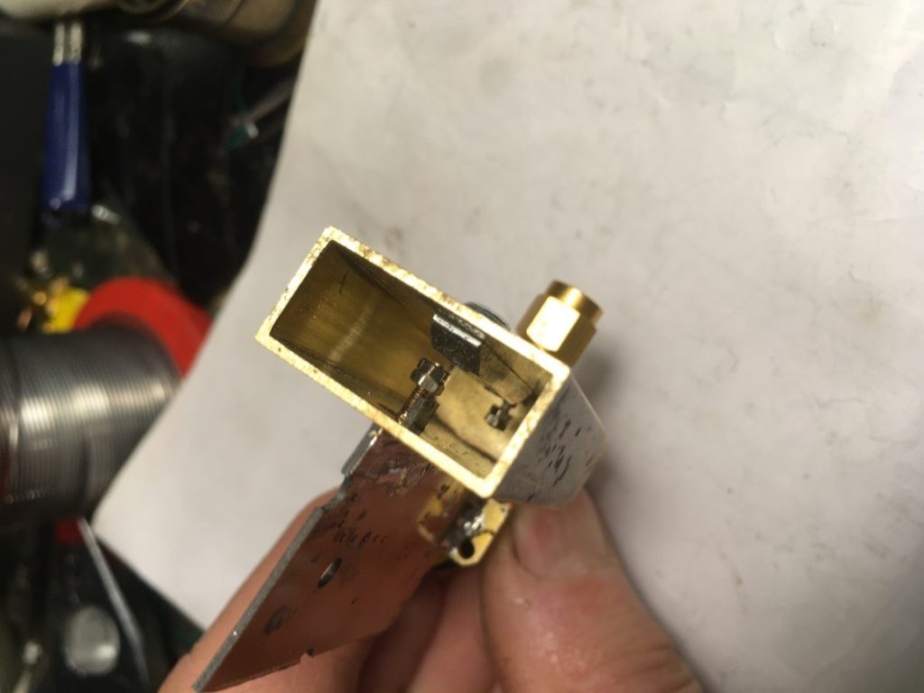
As an exercise, in order not to do the same things, I added a ridge to lower the cut-off frequency and a fat coax transition in order to broadband the filter.
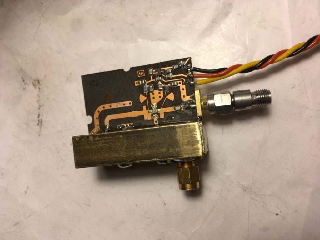
With the addition of an amplifier from surplus RF microwave
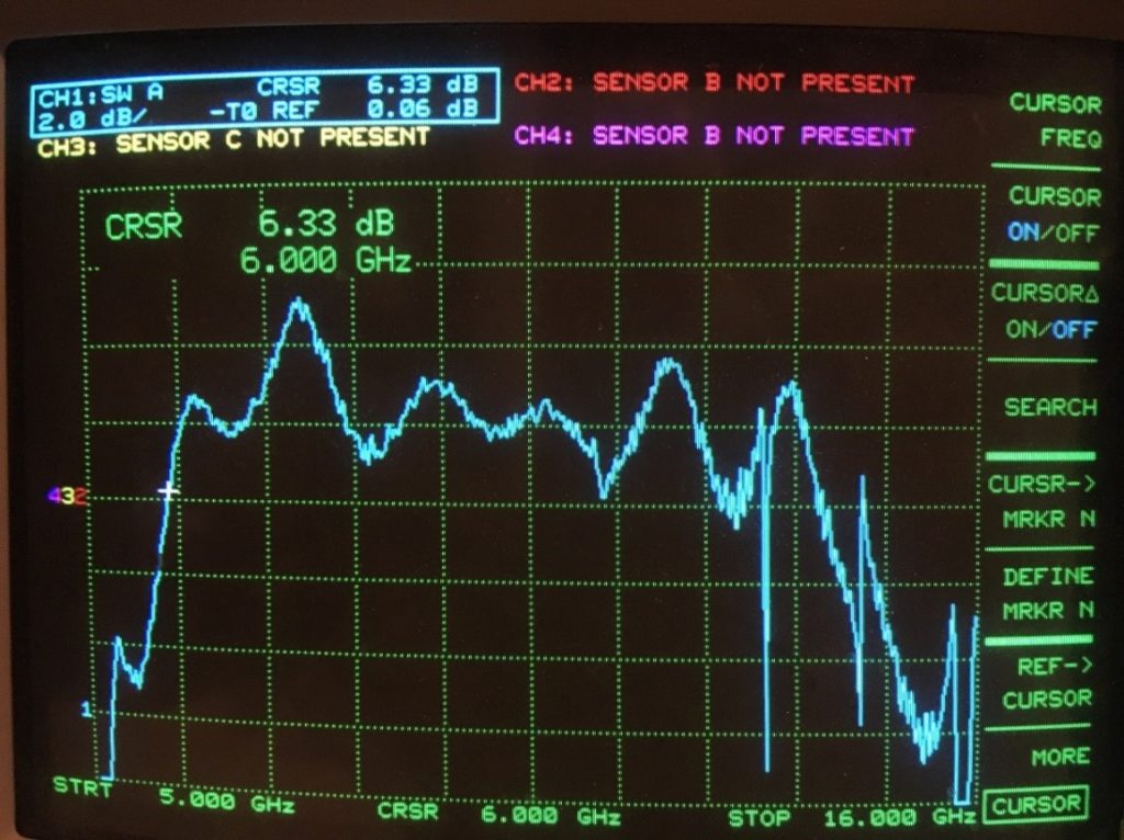
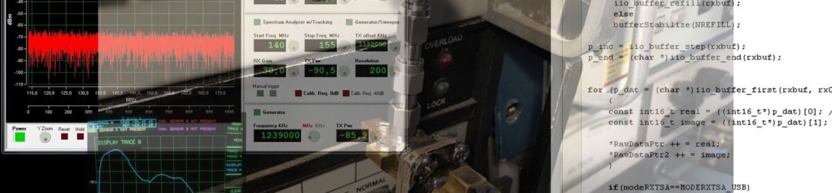
This is the result of a high pass filter with gain.
The same DR filter measurement
With a lot more dynamic range

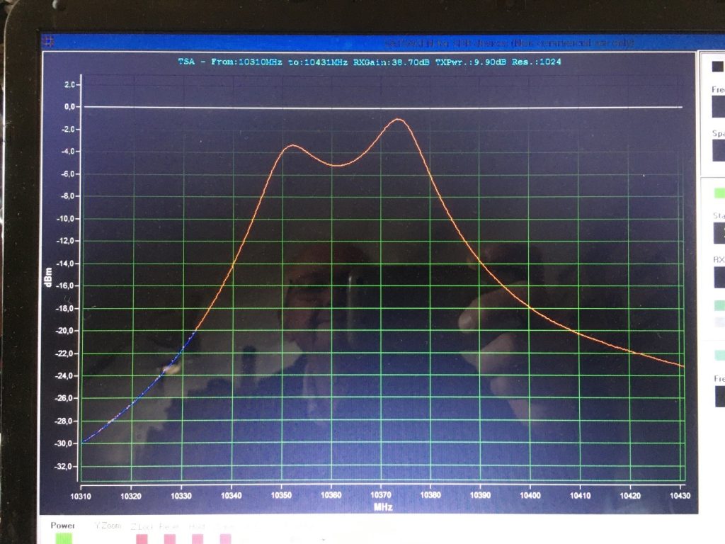
If you add an extra amplifier at the RX port
With a reduction of the TX power, that is useful to reduce the part of RF that cross-talks inside Pluto,
To stay in linear mode.
This is the total dynamic range after a calibration plus the reflected image of myself; the phone is an easy way to take pictures, but no way to use the powerful tools that Alberto provides….
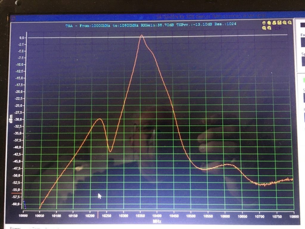
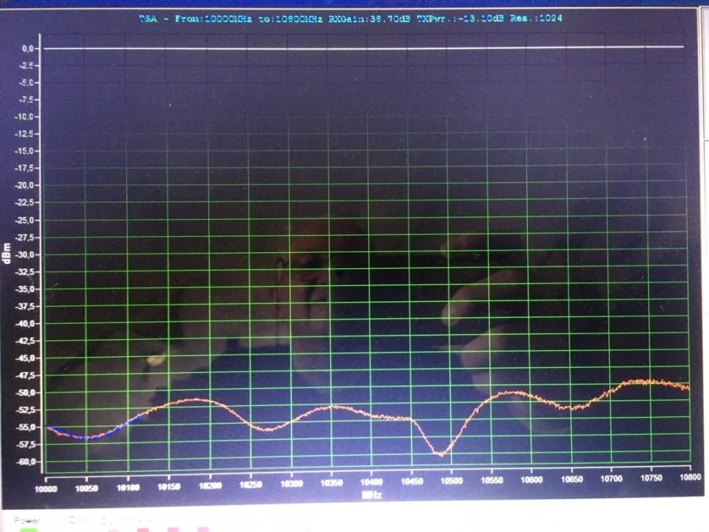
The same DR filter, the jump over the zero is due to the impedance mismatch.
A couple of small attenuators solve the problem.
Remember that a 3 dB attenuator adds 6 dB to the return loss; 6 dB adds 12dB, so up to you without
reducing too much the dynamic range.
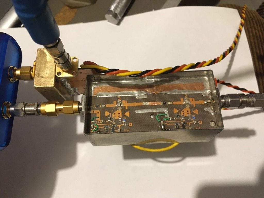
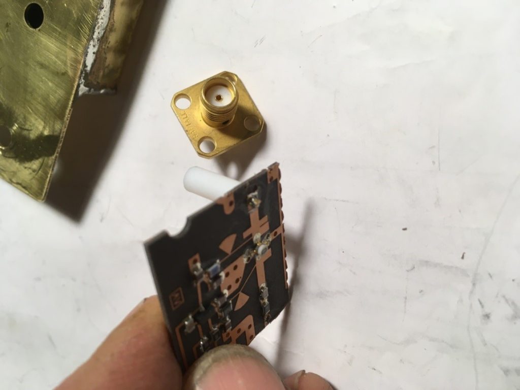
The inside of the amplifier, again, the same surplus parts
The other design
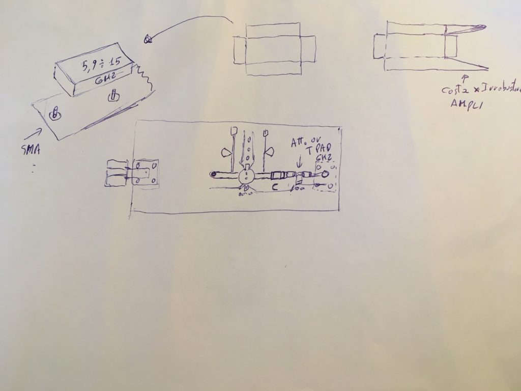
If someone wants to produce a PCB.
The waveguide is a little larger than a WR90 to have a cut-off frequency of 6 GHz
Otherwise use the same surplus amplifier
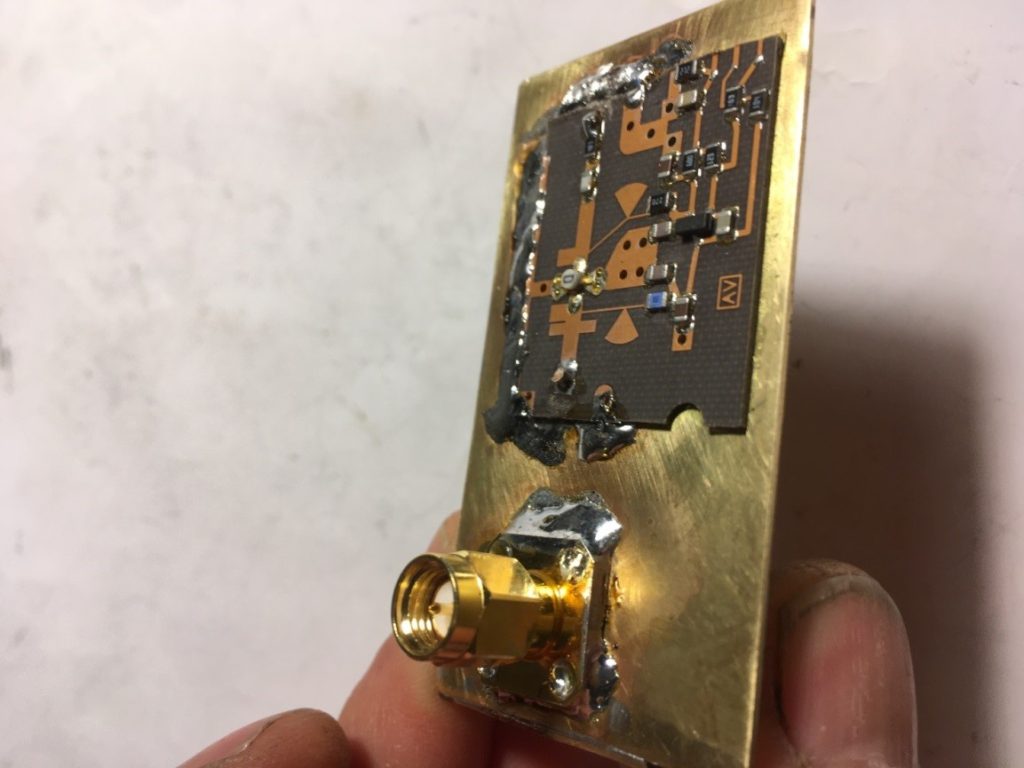
All soldered together
The output of the amplifier
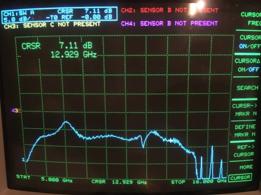
The amplified filter is quite similar to the previous one (the scale is different from 5 dB vs. 2 dB of the other picture)
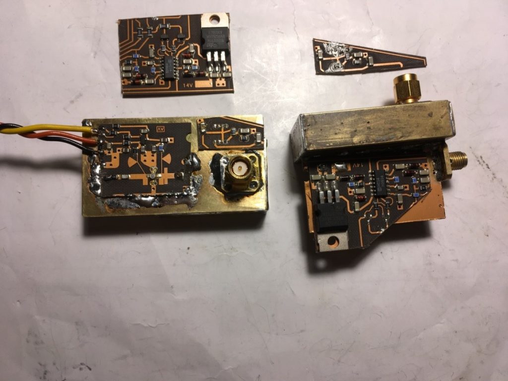
Boards are as PIGS noting to throw, so why not reuse its power supply…..