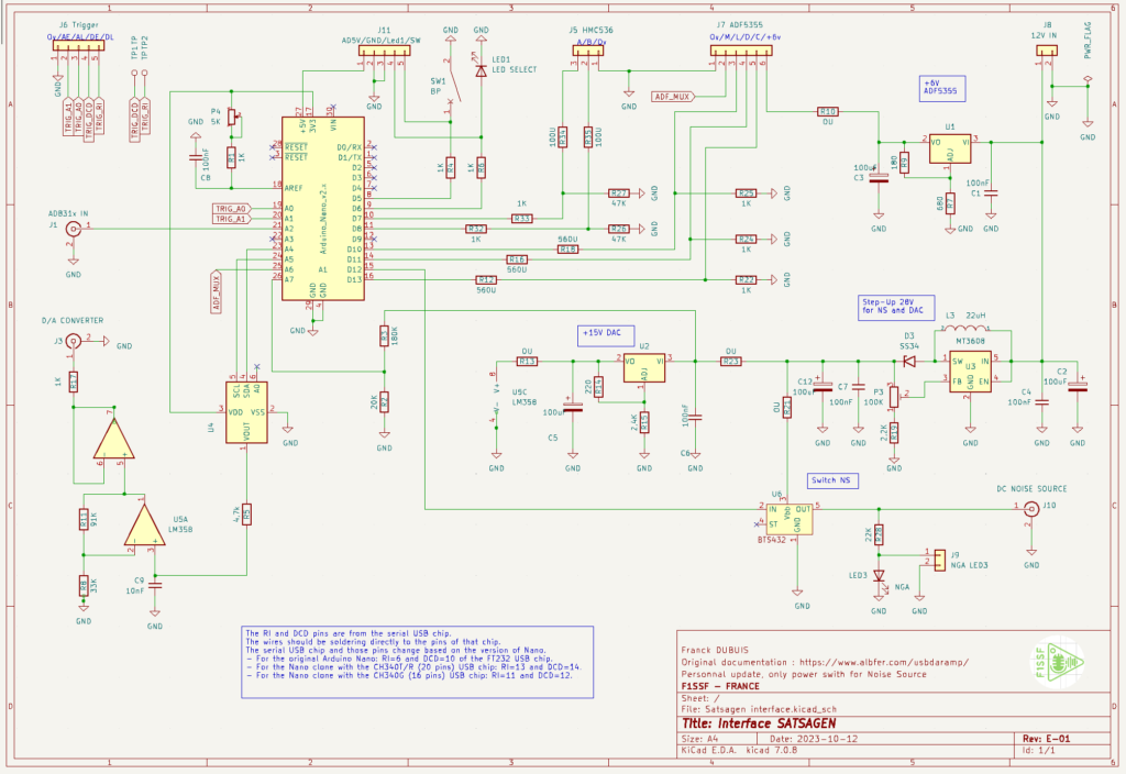
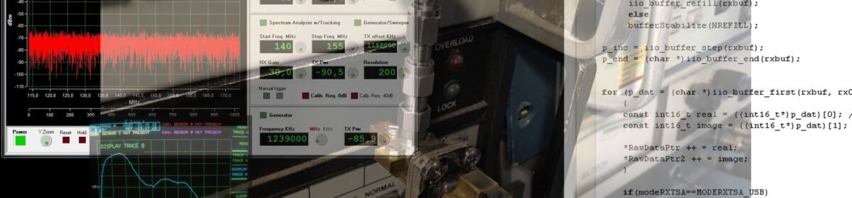
Franck F1SSF ha prodotto un interessante circuito stampato che raccoglie tutte le interfacce del progetto USBDAALBFER (Video).
Con il PCB di Franck e Satsagen si può:
- Alimentare un Noise Source per effettuare misure di Noise Figure and Gain Analyzer.
- Collegare una scheda ADF5355 PLL synthesizer ed usarla come un dispositivo TX di Satsagen
- Collegare una scheda AD831x log detectors per effettuare misurazioni di potenza fino a 10 GHz
- Ottenere degli ingressi digitali ed analogici per utilizzare gli spectrum analyzer triggers
- Pilotare SNA esterni con una rampa da 0 a 10 V sincronizzata con le scansioni SNA/VNA di Satsagen
- Connettere un RF switch per abilitare le due porte effettive nella modalità VNA
Scarica i Gerber files o se vuoi puoi contattare Franck F1SSF, ma la disponibilità di PCB è limitata perché non ha un vero e proprio stock.
Scarica lo sketch Arduino da compilare e caricare sull’interfaccia.
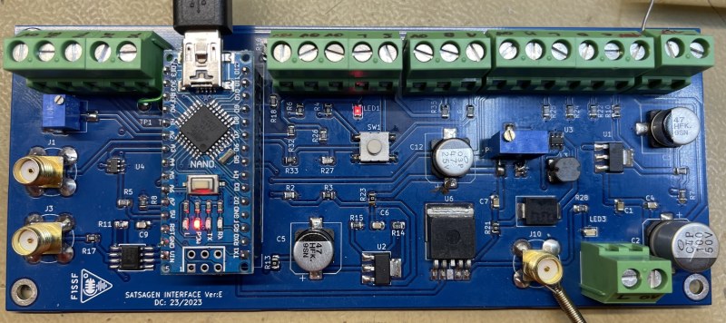
Di seguito le istruzioni di Franck sul montaggio e calibrazione della sua realizzazione:
Hi All, Some information here. This PCBA is the first realization:
- Inserted components except Nano and resistors 0U:
- Use IBom:
- Power UP:
- Power supply on 12V IN connector
- ADF5355 power supply
- Measure R10 pad = 6V, if OK solder R10=0U
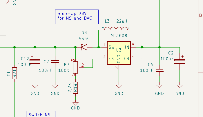
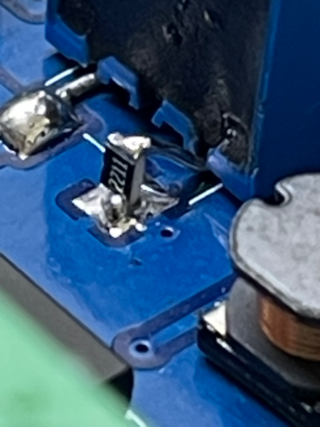
- Step Up 28V – Warning, add modify R19 as below picture
- Measure R23 pad, adjust P3 to obtain 28V max, If OK solder R23=0
- Detector Step Up = ON:
- Measure divider R2/R3, you must have 3Vmax
- +15V DAC
- Measure R13 pad = 15V, if OK solder R13=0U
- Power OFF
- Solder wires directly on serial chip Arduino (see schematic for pin numbers)
- Plug Arduino on support for removal easily, and solder wires DCD = TP1, RI=TP2
- Check the values of the ADF5355 voltage dividers
- R12/R22. R16/R24. R18/R25
- Now you can connect all peripherals
- Use connectors J6 , J11, J5, J7, J10
- +3V ref
- Adjust P4 to have +3V on Arduino pin ref N°18
- Configure Satsagen in tracking mode 0 to 6Ghz
- See on J3 voltage ramp from 0V to about 12V.
SW1 allows you to select the operating modes of the Arduino, depending on the use.
You can deport SW1, LED1, and LED3 on the front end with J11 and J9.
If you move the LEDs, then remove the SMD LEDs or if you leave them, then change the R6 and R22 to adapt the current. SW1 can stay on board.
J1 / J2 / J10 Footprints are BNC connectors, but you can use SMA connectors after cutting legs. You solder ground around directly around the body.
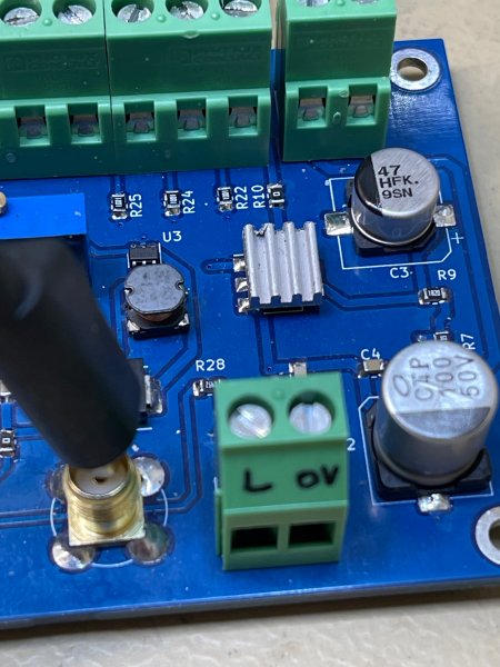
Because the ADF5355 consumes approximately 200mA, it is recommended not to exceed 12V power supply to reduce the dissipation of the 6V regulator. I added a small radiator with thermal glue.
If your RF switch HMC536 already contains 100U resistors on ports A and B under the shield, replace R34 and R35 with 0U.
73’s Franck F1SSF